Gas Turbine Power Plant Block Diagram

Schematic Diagram Of A Simple Gas Turbine Power Plant Download Scientific Diagram

1 Flow Diagram Of A Simple Gas Turbine Power Plant Download Scientific Diagram

Gas Turbine Power Plant Electrical4u

Schematic Diagram Of A Simple Gas Turbine Power Plant Download Scientific Diagram
Gas Turbine Power Plant Working Of Gas Turbine Power Plant
Gas Turbine Power Plant Layout Schematic Diagram
Intro block diagram pv diagram ts property diagram proceses open cycle close cycle energy flow eq s of different components.
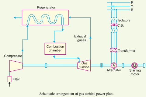
Gas turbine power plant block diagram. A downstream turbine on the same shaft as the compressor. Air compressor used in a gas turbine power plant is mainly of the rotary type. The air filter is attached at the inlet of the compressor where air gets filtered from dust. Some of these pollutants such as sulfur can be turned into re usable byproducts through the claus process.
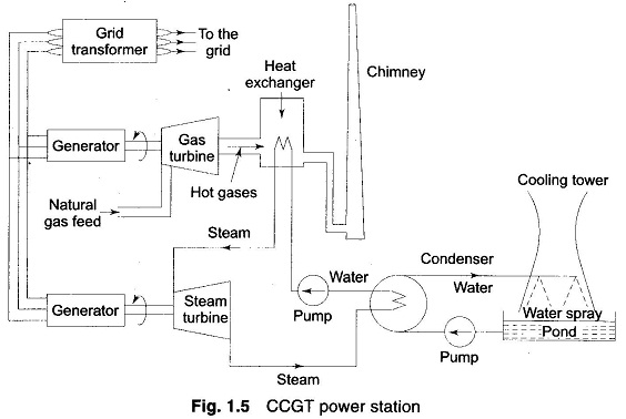
In a gas turbine power plant air is used as the working fluid the air is compressed by the compressor and is led to the combustion chamber where heat is added to the air thus raising its temperature. A fourth component is often used to increase efficiency on turboprops and turbofans to convert power into mechanical or. Gas turbine power plants. The waste heat from the gas turbine is routed to the nearby steam turbine which generates extra power.
Gas turbine working principle. Figure 1 2 ausc coal plus gas turbine heat recovery boiler power plant block diagram concept 2 1 2 plant capacity the ausc coal plant steam cycle has a gross generation capacity of 300 mw in both concept 1. The main components of a gas turbine power plant are the. The following one line diagram shows a typical power plant electrical distribution system.
Modern gas turbines usually use liquid fuel but they may also use gaseous fuel natural gas or gas produced artificially by. A gas turbine also called a combustion turbine is a type of continuous and internal combustion engine the main elements common to all gas turbine engines are. Some of the plants utilize fossil fuels such as coal oil and natural gas to fire boilers as tall as a twenty five story building. An integrated gasification combined cycle igcc is a technology that uses a high pressure gasifier to turn coal and other carbon based fuels into pressurized gas synthesis gas it can then remove impurities from the syngas prior to the power generation cycle.
Block diagram of coal based thermal power plant. 2020 3 12 a block diagram of the overall plant is shown in figure 1 2. Inner workings of a combined cycle power plant. A combined cycle power plant uses both a gas and a steam turbine together to produce up to 50 percent more electricity from the same fuel than a traditional simple cycle plant.
Gas turbine engines derive their power from burning fuel in a combustion chamber and using the fast flowing combustion gases to drive a turbine in much the same way as the high pressure steam drives a steam turbine. In the combustion chamber the compressed air combines with fuel and the resulting mixture is burnt. August 31 2013 6 unit iii power plant engineering gas turbine power plant combustion chamber. The greater the pressure of air the better the fuel air mixture burns.
A generating station which employs a gas turbine as the prime mover for the generation of electrical energy is known as a gas turbine power plant. In this video we will discuss about gas turbine power plant. An upstream rotating gas compressor.

2 Power Technology Energy News And Market Analysis
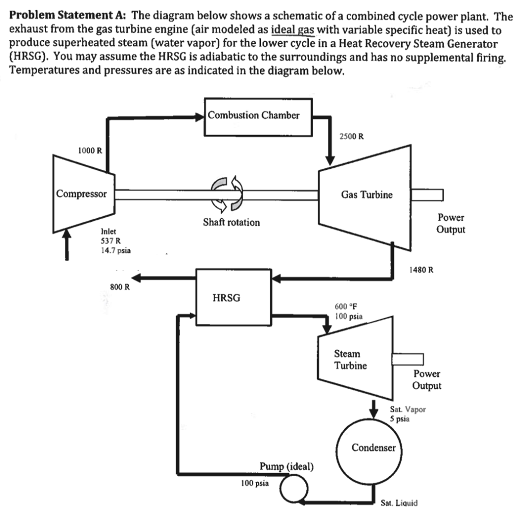
Problem Statement A The Diagram Below Shows A Sch Chegg Com

Gas Turbine Power Plants

Advanced Gas Turbine Design Power Generation Technologies

Basic Control System Block Diagram Of A Gas Turbine Download Scientific Diagram

Combined Cycle Power Plants Power Generation Technologies

Schematic Diagram Of A Simple Gas Turbine Power Plant Download Scientific Diagram

Open Cycle Gas Turbines Ipieca
Gas Turbine Power Plants

Simple Cycle Gas Plant Energy Education
Performance Of Gas Turbine Power Plant

Gas Turbine Plant Model Block Diagram Each Block Transfer Functions Download Scientific Diagram

Micro Gas Turbine An Overview Sciencedirect Topics
