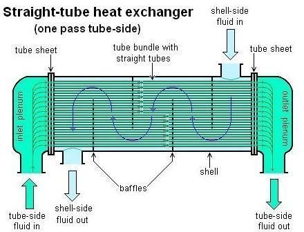
Double Pipe Heat Exchanger Schematic Diagram
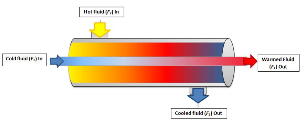
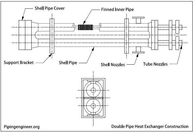
A double pipe heat exchanger consists of one pipe inside another.
Double pipe heat exchanger schematic diagram. Heat exchangers are devices designed to transfer heat between two or more fluids i e liquids vapors or gases of different temperatures. It is called a double pipe exchanger because one fluid flows inside a pipe and the other fluid flows between that pipe and another pipe that surrounds the first. The double pipe heat exchanger is one of the simplest types of heat exchangers. Double pipe heat exchanger.
These would always be longitudinal fins rather than the more common radial fins used in a cross flow finned tube heat exchanger. 22 kb tabela nomenklaturowa tema png 1 653 2 339. D double pipe exchanger. A picture of a double pipe heat exchanger is shown at the right.
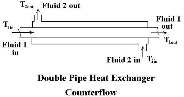
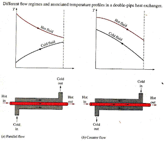
24 kb t vs x diagram of hot stream water and cold stream r11 in heat exchanger png 560 427. Figure 5 illustrates the spiral exchanger configuration. It can be operated as a parallel flow or as a counterflow heat exchanger. T vs h diagram heat exchanger with internal pinch png 524 441.
Schematic of crbr intermediate heat exchanger ihx the tubes in this single pass counterflow shell and tube heat exchanger were over 25 7 5m long. A piping and instrumentation diagram p id is a detailed diagram in the process industry which shows the piping and process equipment together with the instrumentation and control devices. Depending on the type of heat exchanger employed the heat transferring process can be gas to gas liquid to gas or liquid to liquid and. The double pipe exchanger is used when one liquid has a greater resistance to heat flow than another r when the surface area is small.
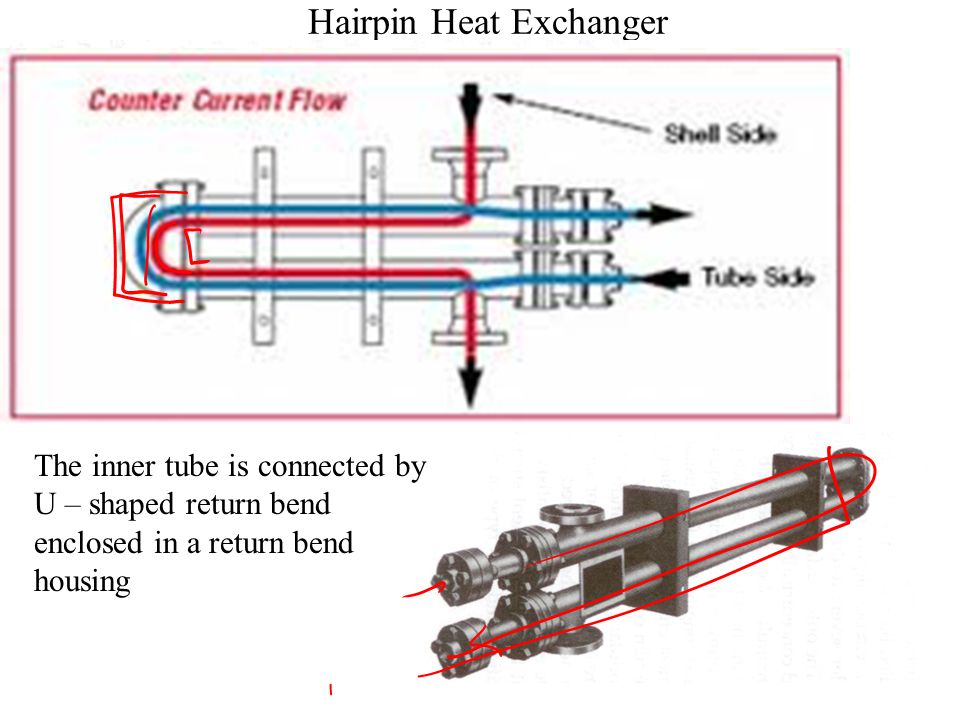
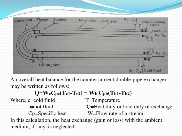
These heat exchangers are generally designed fabricated inspected and tested as per api 660 en iso 16812 tema. Double pipe heat exchanger design requires use of the heat transfer rate the log mean temperature difference and an estimate of the overall heat transfer coefficient to calculate the estimated heat transfer surface area. This is a concentric tube construction. Both pipes have a return bend at one end.
A double pipe heat exchanger is usually operated as a counter flow heat exchanger as shown in the diagram at the left. Superordinate to the p id is the process flow diagram pfd which indicates the more general flow of plant processes and the relationship between major equipment of a plant facility. In a double pipe heat exchanger design an important factor is the type of flow pattern in the heat exchanger. A close up view of a section of a water to air heat exchanger.
As indicated in figure 7 the double pipe exchanger consists of a pipe within a pipe. The flow pattern in a shell and tube heat exchanger with a single tube. Some heat exchanger advertises the availability of finned tubes in a hairpin or double pipe heat exchanger. Flow in a double pipe heat exchanger can be co current or.


